Component evidence
Representative parts, variants and difficult behaviours drive the technical route before equipment is committed.
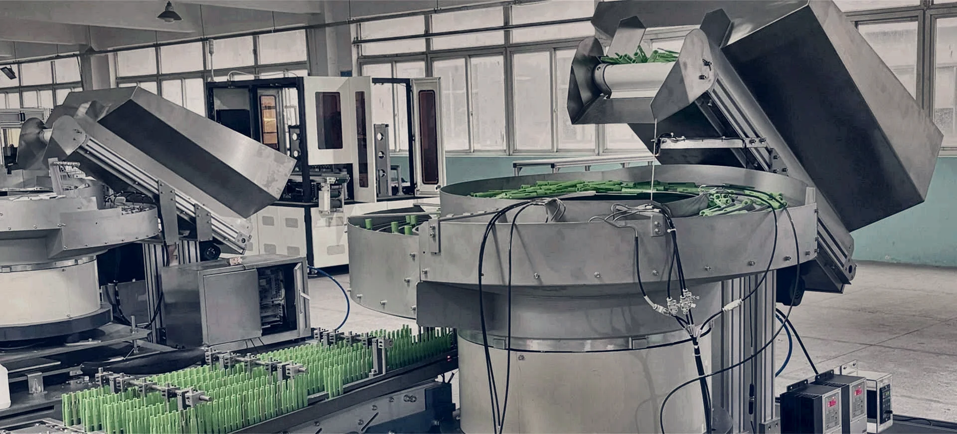
TURNKEY PROJECT INTEGRATION
Coordinate feeding, inspection, buffering, controls, guarding and acceptance around the production result—without leaving the critical interfaces between separate packages.
DIRECT ANSWER
A parts feeding systems integrator makes the full component route operate as one recoverable production system rather than a collection of machines.
The work can include component trials, feeding-method selection, layout, inspection, buffering, robotics, PLC and HMI controls, guarding, the receiving-machine interface, factory acceptance, installation and commissioning. The integration boundary is agreed before manufacture so each physical, software and safety responsibility has an owner.
WHY INTEGRATION MATTERS
A strong project closes the gaps that a standalone equipment specification can miss.
Representative parts, variants and difficult behaviours drive the technical route before equipment is committed.
Position, orientation, pitch, datum, accepted condition and ownership are defined at the receiving process.
Feeding, inspection, buffering and downstream demand are assessed as sustained operating states, not isolated peak rates.
Demand, ready, blocked, starved, fault, reset, recipe and diagnostic signals are assigned to the correct controller.
Guarding, interlocks, stops, reset zones and safe recovery access are developed with the final cell layout.
The test plan proves the agreed output, variants, operating states, recovery and machine interface before handover.
RESPONSIBILITY MAP
Use the responsibility table during concept approval and again before the factory acceptance plan is frozen.
| Project area | Decision to record | Evidence or deliverable |
|---|---|---|
| Component family | Which variants and production variation must run? | Sample register, drawings and agreed trial population |
| Feeding architecture | Which principle controls separation and orientation? | Trial evidence, concept description and capacity basis |
| Machine hand-off | Where does responsibility pass to the receiving process? | Signed interface drawing and datum definition |
| Controls and data | Which PLC owns states, recipes, alarms and records? | I/O schedule, network map and functional description |
| Guarding and safety | Where are stops, reset zones and access boundaries? | Risk-assessment inputs and safety-interface schedule |
| Acceptance | What result proves the integrated scope? | FAT and site-acceptance protocol with responsibilities |
WHEN TO USE AN INTEGRATED SCOPE
These project conditions justify early integration planning even when the feeder itself appears straightforward.
The feeder must connect to a fixed datum, legacy controls and a limited production shutdown.
Multiple feeders must stay synchronised with recipes, assembly sequence and shared fault recovery.
Accepted, rejected and unverified parts need controlled routing and a defined result owner.
Vision, pick access, gripper design, cycle time and downstream placement must be balanced together.
Feeder access and production-machine access sit inside one safety concept and recovery sequence.
The customer needs a proven production hand-off rather than a feeder tested in isolation.
PROJECT GATES
A staged route reduces the cost of changing the architecture after detailed design.
Record components, variants, accepted hand-off, rate, environment and downstream operating states.
Test uncertain component behaviour and establish the credible feeding and inspection route.
Approve layout, interface, responsibility, controls, guarding, access and acceptance basis.
Develop tooling, software, diagnostics, documentation and installation requirements.
Prove the offline scope, connect site-dependent interfaces and close agreed acceptance actions.
RELATED PROJECT ROUTES
These detailed routes help define the application before a project review.
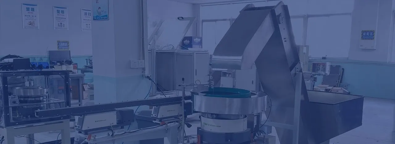 RETROFIT
Define the hand-off, PLC signals, guarding and shutdown plan.
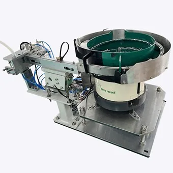 MULTIPLE FEEDS
Coordinate several components around one assembly recipe and cycle.
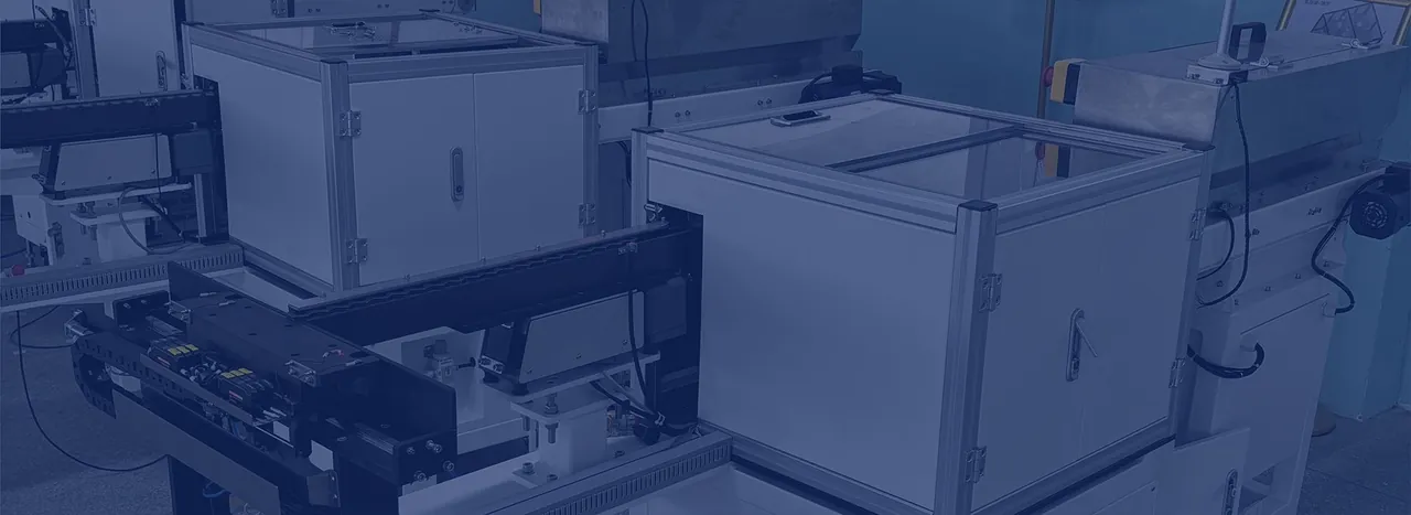 VARIANT CONTROL
Select the right combination of dedicated, flexible and hybrid presentation.
COMMON QUESTIONS
Final scope depends on the application evidence, receiving machine and agreed responsibility boundary.
A parts feeding systems integrator coordinates the complete route from bulk components to the receiving production machine. The role can include application trials, technology selection, mechanical interfaces, inspection, buffering, PLC and HMI controls, guarding, factory acceptance, installation and commissioning.
Integration is especially valuable when the project includes an existing machine, several component feeds, inspection or robotics, a shared safety system, a difficult hand-off or measurable line-level acceptance requirements.
Ownership must be stated in the project specification. A clear interface schedule should define the physical datum, signals, software changes, guarding boundary, installation work, testing responsibilities and acceptance point for each party.
The acceptance plan should test agreed components and variants, sustained accepted output, replenishment, inspection, buffering, faults, recovery, changeover, controls, safety functions and the defined machine hand-off. Site-dependent interfaces are then confirmed during commissioning.
INTEGRATION REVIEW
Send the component family, required hand-off, target output, receiving-machine information and available layout for an initial review.