Bulk storage & replenishment
Low-level loading, hopper capacity and metered delivery control bed depth and reduce unnecessary operator intervention.
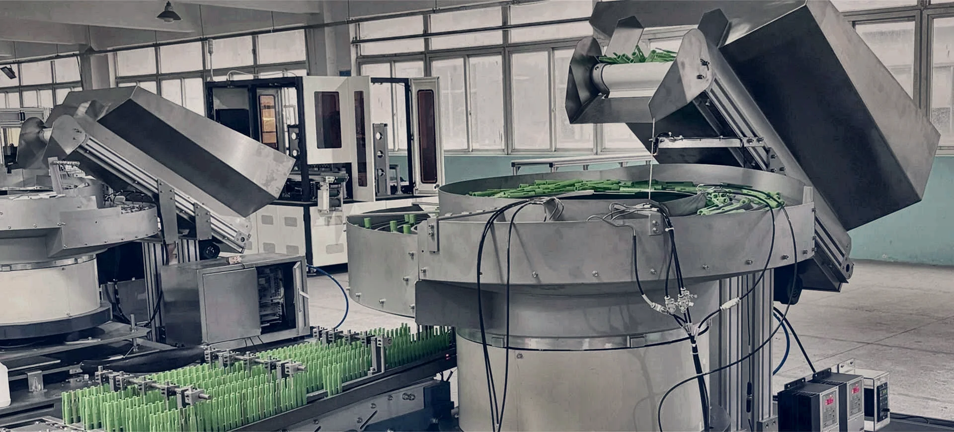
COMPLETE FEEDING CELLS
Combine every stage—from bulk loading to verified release—under one technical scope, one controls philosophy and one acceptance plan.
TURNKEY INTEGRATION
A complete automated parts feeding system starts with the condition required by the receiving machine: part position, orientation, datum, pitch, accepted quality and sustained demand.
Working backwards from that interface allows bulk storage, separation, orientation, inspection, buffering and singulation to be sized as one sequence. It also exposes the controls and safety boundaries early enough to engineer them properly.
CELL ARCHITECTURE
The exact technology varies by component, but the engineering duties remain consistent across robust feeding systems.
Low-level loading, hopper capacity and metered delivery control bed depth and reduce unnecessary operator intervention.
Dedicated tooling, controlled rotary movement, stepped elevation or flexible presentation creates valid part states.
Sensors or vision confirm selected features and remove or recirculate incorrect components before hand-off.
A controlled queue protects the process cycle without creating damaging pressure, shingling or lock-ups.
Escapements, pick points or robot logic present one accepted component only when the downstream station is ready.
PLC sequences, alarms, safety functions, recovery access and maintenance needs are included in the equipment layout.
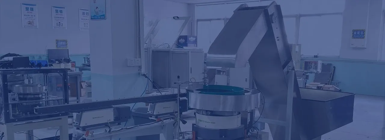
THE APPLICATION BASIS
Small variations in geometry, moulding, surface finish, oil, static or presentation can change feeder behaviour. The application basis should capture normal production variation—not only ideal samples.
SELECTION ROUTES
No single feeding technology is best for every part. Trials and interface requirements determine the most reliable architecture.
| Feeding principle | Typical strength | Important project checks |
|---|---|---|
| Vibratory bowl | Dedicated, repeatable orientation of stable part families | Tangling, recirculation, surface marking, tooling access and noise |
| Centrifugal | High continuous flow for suitable robust components | Geometry, rotational handling, changeovers and downstream queue control |
| Step feeder | Lower-vibration elevation of larger or tangle-prone parts | Part length, step geometry, return path, enclosure and loading height |
| Flexible / robotic | Frequent variants, complex orientation and controlled placement | Image contrast, grasp access, cycle time, re-presentation and recovery |
COMPLETE-PROJECT ROUTES
Use the systems-integrator guide for one accountable project boundary, the multi-component guide for several assembly inputs, or the high-mix guide for frequent variant change.
INTEGRATIONDefine project scope, interfaces, controls, safety and acceptance ownership.
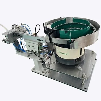 MULTIPLE INPUTS
Balance several feeders and verification points around one assembly cycle.
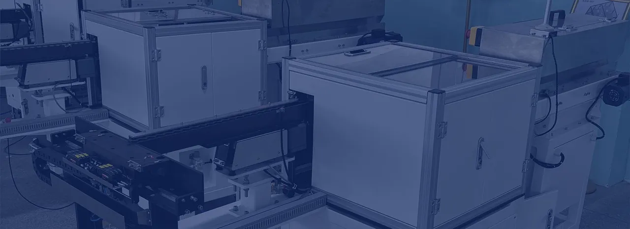 PRODUCT VARIETY
Compare dedicated, change-part, flexible, tray and hybrid architectures.
PROJECT ASSESSMENT
We will help define the right starting architecture, the evidence needed for selection and the interfaces that belong in the project scope.
An automated parts feeding system takes components from bulk, separates and orients them, controls accumulation and presents one verified part to the next machine. The right feeding principle depends on the component, sustainable rate, product mix and required hand-off.