Dedicated orientation
Use mechanical tooling for stable, repeatable components where rate and fixed presentation dominate.
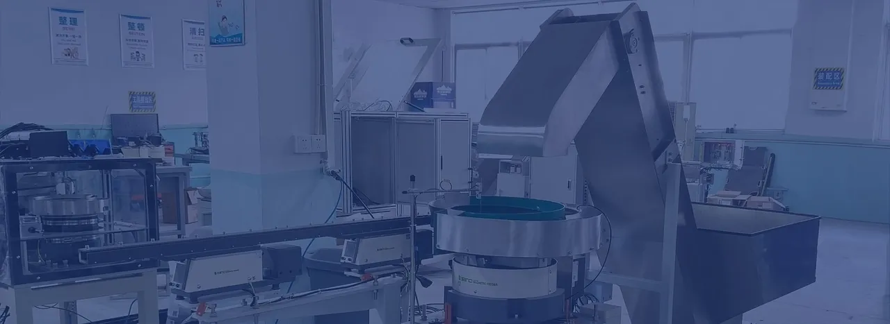
COORDINATED ASSEMBLY INPUTS
Bring screws, pins, inserts, seals, mouldings and other inputs to the right station in the right recipe—without letting one unstable feed path stop the complete cell.
DIRECT ANSWER
A multi-component feeding system supplies two or more different parts to one assembly, kitting or production process.
Each component can use the feeding method that best fits its geometry and required presentation. A common controls architecture then coordinates recipe selection, station demand, component verification, buffering, release, alarms and completion. The useful result is a complete assembly cycle with every required part available—not several feeders passing isolated rate tests.
CELL ARCHITECTURE
The individual feed paths can differ while the production logic remains common.
Use mechanical tooling for stable, repeatable components where rate and fixed presentation dominate.
Use vision-guided robotic feeding where compatible variants or complex reorientation justify programmability.
Retain controlled incoming presentation for delicate, tightly toleranced or low-volume parts when appropriate.
Size each queue around demand, refill behaviour, part pressure and the consequence of a brief interruption.
Confirm the correct part and valid presentation before it enters the assembly or kit sequence.
Coordinate recipes, interlocks, starved and blocked states, recovery and production result in one operating model.
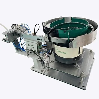
THE BOTTLENECK TEST
Fast individual feeders do not guarantee a balanced assembly cell. Every channel must recover from replenishment, recirculation, a short downstream stop and the normal component variation expected in production.
RECIPE & ERROR-PROOFING
The control philosophy should prevent a valid feed action from creating the wrong assembly.
List every finished-product recipe and the components, quantities and orientations it requires.
Define which controller selects the recipe and how feeder settings and change parts are verified.
Use suitable sensors or vision where presence, orientation, variant or selected features can be detected reliably.
Interlock each component demand and confirmation with the assembly state and downstream readiness.
Define what happens when a part is missing, unverified, dropped or rejected after the cycle begins.
Check cleared queues, correct tooling, recipe selection and first-off acceptance before production restarts.
SPECIFICATION TABLE
Complete one row per component, then add the shared assembly and recovery requirements.
| Input | Question to answer | Why it matters |
|---|---|---|
| Component family | Which variants, suppliers and acceptable variation exist? | Determines tooling, recipes, inspection and trials |
| Presentation | What orientation, datum and release condition are required? | Defines the final tooling and assembly interface |
| Demand | How often and in what sequence is the part requested? | Sets sustained output and buffer requirements |
| Verification | Which missing, wrong or malformed states must be detected? | Defines sensing, vision and reject handling |
| Changeover | What must be cleared, changed, selected and confirmed? | Controls downtime and wrong-part risk |
| Fault recovery | Can an incomplete cycle be recovered or must it be rejected? | Shapes cell logic, traceability and operator actions |
COMMON QUESTIONS
Final architecture depends on representative components and the complete assembly sequence.
A multi-component feeding system supplies two or more different parts to one assembly, kitting or production process. Each component can use its own feeding method, buffer and verification, while a common controller coordinates recipes, demand, release, faults and completion.
Yes. A cell can combine bowl, step, centrifugal, linear, tray, flexible or robotic presentation where each method suits its component. The controls and acceptance plan must verify that the complete sequence remains balanced.
Recipe control, part-present sensors, selected feature inspection, release confirmation and assembly-sequence interlocks can be combined. The exact error-proofing method depends on what can be detected reliably in the application.
The complete cell is tested under representative demand with all feed channels operating, including replenishment, normal recirculation, brief stops, buffer recovery, changeover and agreed fault conditions. The slowest or least stable path must not be hidden by isolated feeder tests.
ASSEMBLY CELL REVIEW
Send the finished assembly sequence, component matrix, required cycle, presentation points and error-proofing requirements for an initial review.