TECHNICAL FAQ
Straight answers to common automated parts feeding questions.
Use these answers to prepare a clearer project brief. Final equipment selection and performance remain subject to representative samples and the agreed interface.
What is an automated parts feeding system?
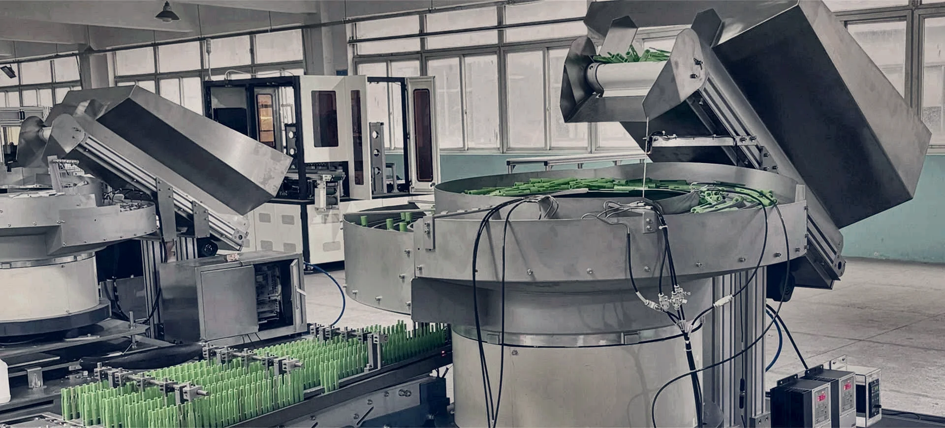
An automated parts feeding system is the complete equipment path that takes loose components from bulk storage and delivers them to a production machine in a defined orientation, position and condition. It may include a hopper, feeder, tracks, inspection, buffering, escapements, robotics, controls and guarding.
Do you supply complete cells rather than individual feeders?
Yes. The focus is complete automation projects. The scope can cover component trials, the selected feeding method, inspection, controls, guarding, downstream interfaces, factory acceptance testing, installation and commissioning.
How do you select the feeding method?
Selection depends on geometry, mass, material, finish, nesting or tangling behaviour, required orientation, sustained accepted output, product range and the downstream hand-off. Representative production samples are normally required.
Can a feeding cell connect to existing machinery?
Usually, subject to an interface review covering the physical hand-off, footprint, controls signals, safety boundary, buffer strategy, access and responsibility for any modifications.
How is system output proven?
Output should be measured as sustained accepted parts at the agreed hand-off condition, not as a theoretical feeder peak. FAT can include normal replenishment, buffer behaviour, faults, recovery, changeover and agreed sample variation.
What components can be fed automatically?
Common applications include screws, nuts, washers, pins, inserts, springs, clips, connectors, seals, grommets, caps, closures, fitments, mouldings and many other production components. Suitability is confirmed from the actual part and process.
Can one feeder run several formats?
Possibly. Stable related variants may use adjustable tooling, change parts or recipes. A wide geometry range or frequent change may favour flexible presentation or separate feeding routes.
What samples should be provided?
Provide representative parts from normal production variation, including all variants, supplier differences and known difficult conditions. Sample quantity is confirmed after the initial review.
How much buffer capacity is needed?
Buffer is sized around downstream demand, feeder recovery, normal replenishment, short stops, queue pressure and the acceptable risk of process starvation.
Can vision check defects?
Only where the required defect or feature is visible with suitable resolution, lighting, contrast and presentation. Good and reject samples are needed to assess feasibility.
Can you integrate guarding and safety?
Guarding, interlocks, safety functions, robot zones, access and responsibility boundaries can be included in the complete project scope, subject to the machinery risk assessment.
What happens after installation?
The agreed scope can include commissioning, training, documentation, spares, maintenance planning and production support.
PROJECT ASSESSMENT
Bring us the component, the rate and the required hand-off.
We will help define the right starting architecture, the evidence needed for selection and the interfaces that belong in the project scope.
How should a parts feeder be matched to an assembly cycle?
Define the required presentation at the assembly station and the demand pattern, including pauses and replenishment. The feeding system needs to support that cycle without damaging or misorienting components. Agree the interface, buffer requirement and response to an unavailable part so the feeder is assessed as part of the assembly process.
- Presentation at assembly
- Demand pattern and buffer
- Missing-part and restart responses
Related guidance: Systems integration · Robotic feeding