Bulk load
Ergonomic storage and metered replenishment sized for the autonomy your line needs.

TURNKEY COMPONENT AUTOMATION
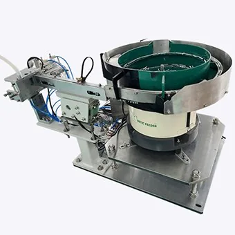
Automated parts feeding links bulk loading, separation, orientation and inspection to the presentation your production machine can accept. Define the part family, required orientation, sustained rate and final hand-off first, then compare the feeding, buffering and robotic stages as one connected system.
THE REAL AUTOMATION CHALLENGE
A production line does not need parts moving around a machine. It needs accepted components available at the exact datum, orientation and rate demanded by the next operation.
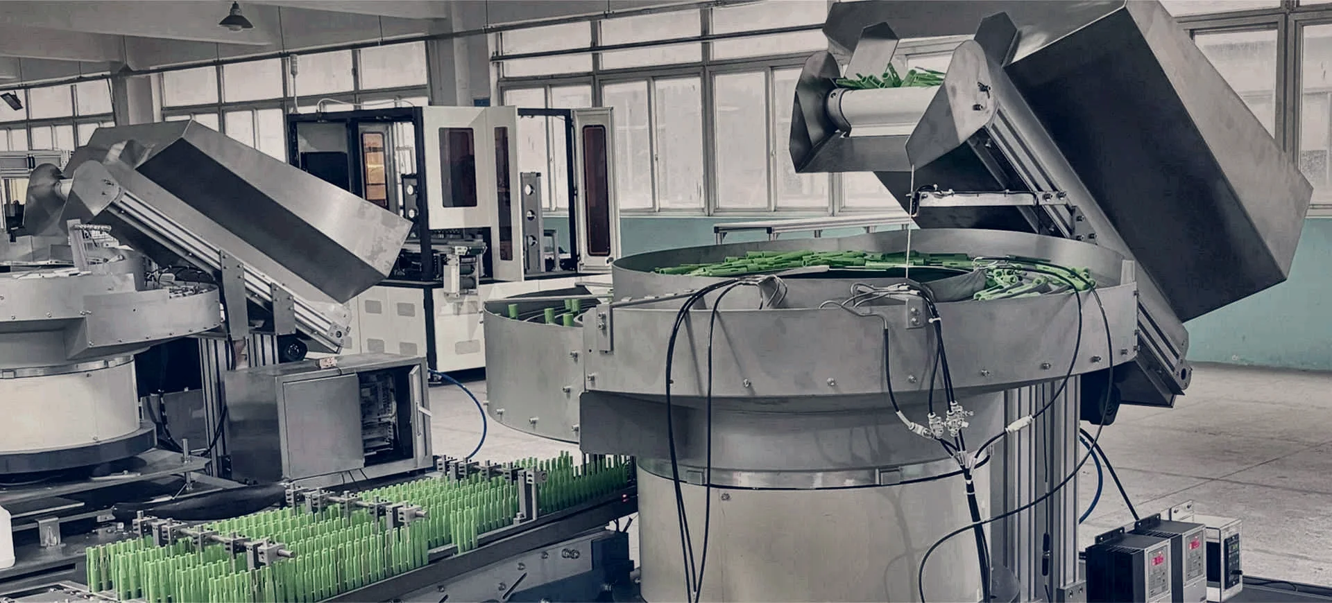
That means designing bulk storage, separation, recirculation, inspection, buffering, one-part release, fault recovery and the controls handshake as one operating sequence—not as disconnected equipment packages.
Explore complete feeding cellsTHE COMPLETE FEED PATH
Every stage is configured around component behaviour, production demand and the receiving machine.
Ergonomic storage and metered replenishment sized for the autonomy your line needs.
Control bed depth, break clusters and create the conditions for reliable orientation.
Mechanical tooling or vision establishes the accepted pose, datum and direction.
Sensors or machine vision verify presence, orientation, colour or selected geometry.
Accumulation protects the downstream cycle from brief feed interruptions and queue pressure.
An escapement or robot releases exactly one accepted component when requested.
The part arrives at the agreed position, condition and rate with a defined controls handshake.
COMPLETE SYSTEM ARCHITECTURES
Technology is selected from the application evidence, then engineered into one deliverable production cell.
 01
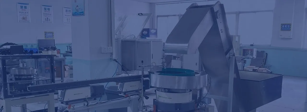
01Dedicated automation
Bulk hoppers, bowl or step feeding, linear accumulation, escapement tooling and controls engineered as one reliable sequence.
Explore complete cells ↗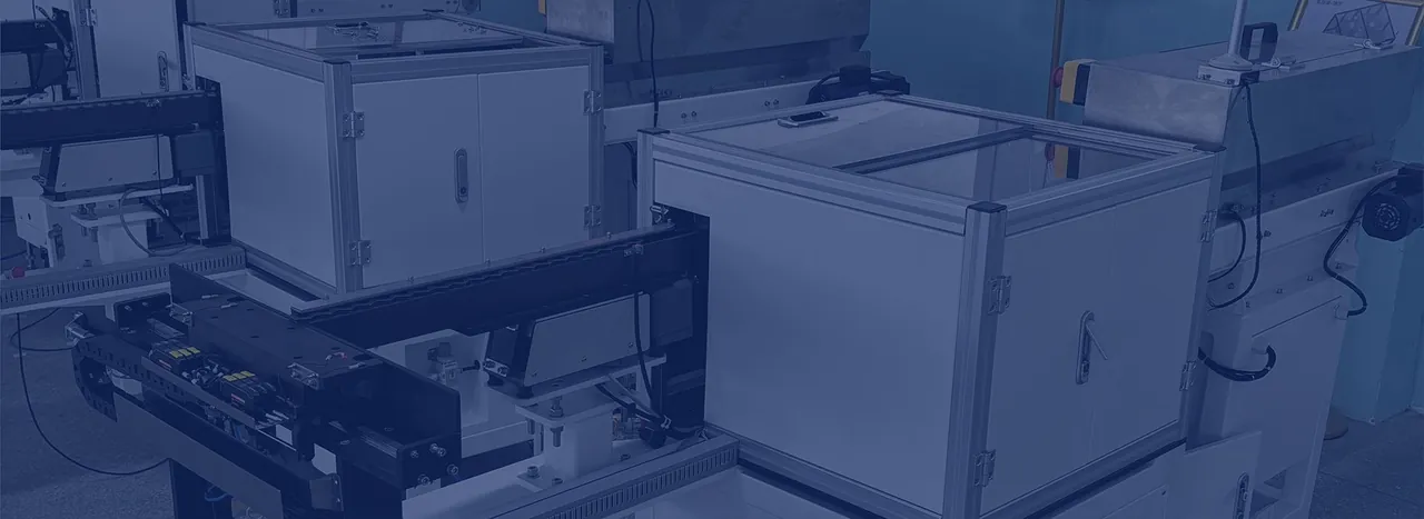 02
02Flexible automation
Camera-located picking, recipe control, end-of-arm tooling and placement for difficult geometries or changing product families.
Explore robotic feeding ↗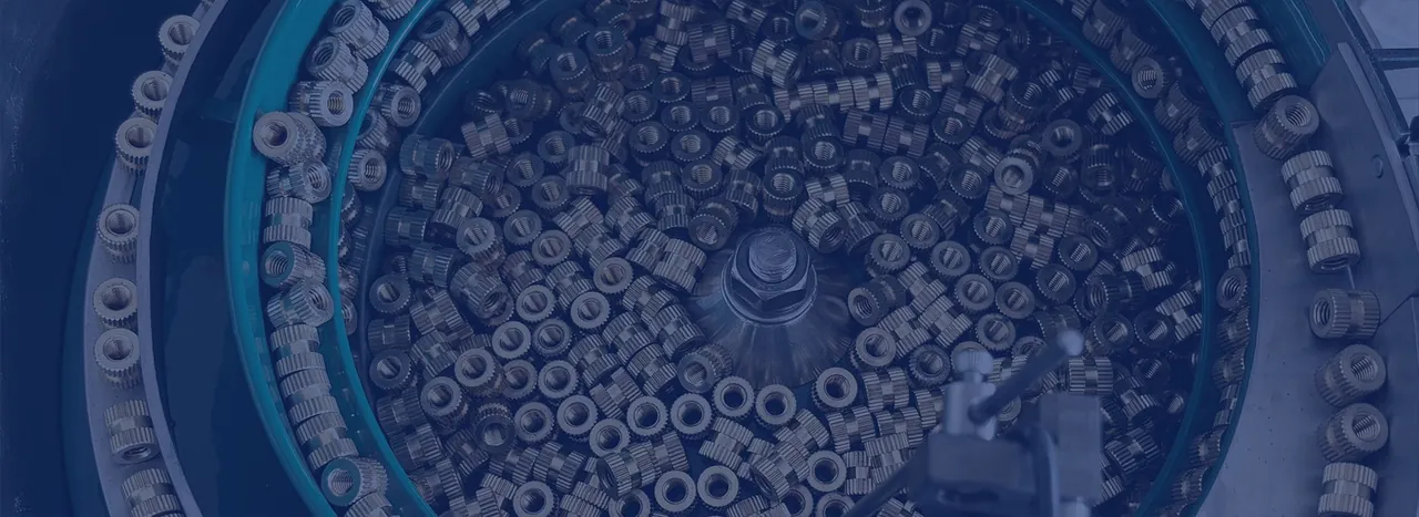 03
03Verified output
Check selected features, reject non-conforming parts, count accepted components and release a proven batch or kit.
Explore counting systems ↗
INTEGRATION WITHOUT THE GAPS
We define the hand-off height, datum, pitch, queue capacity, call signals, ready and fault states, reject handling, access envelope and recovery sequence before the interfaces become expensive to change.
APPLICATIONS
Each solution begins with the real component family, its difficult behaviours and the condition required by the next process.
Fasteners, pins, inserts, springs and pressings presented to drivers, presses and assembly stations.
Explore application ↗Clips, connectors, seals, grommets and moulded parts with variant and orientation control.
Explore application ↗Housings, terminals and precision connectors handled around delicate features and static sensitivity.
Explore application ↗Controlled-contact components with defined cleanability, validation and acceptance needs.
Explore application ↗Caps, closures, scoops, fitments, valves and inserts supplied continuously to packaging machinery.
Explore application ↗Accepted components counted into bags, boxes, kits or an automated assembly sequence.
Explore application ↗PROJECT DELIVERY
A clear, staged route takes the project from sample review to a cell ready for production handover.
Components, variants, drawings, orientation, sustained rate, space, utilities and site standards.
Representative production parts tested against measurable handling and presentation criteria.
Layout, equipment principle, buffers, controls, guarding and responsibility boundaries agreed.
Mechanical tooling, PLC logic, vision recipes, robot paths, documentation and access developed.
Rate, orientation, replenishment, alarms, recovery, changeover and safety checked to the plan.
Installation, commissioning, training, production support and lifecycle requirements.
WHAT TO SEND FIRST
Part photographs and drawings, all variants, material and finish, required orientation, sustained accepted rate, downstream machine details, available space and timescale.
PROJECT PLANNING GUIDES
Use these customer-focused guides to prepare a clearer requirement, compare complete scopes and reduce late project surprises.
 SYSTEMS INTEGRATION
Coordinate trials, equipment, controls, guarding, acceptance and the receiving-machine hand-off.
SPECIFICATION CHECKLISTCapture components, sustained output, hand-off, controls, safety, FAT and acceptance responsibilities.
COST & ROICompare installed scope and calculate return from verified labour, downtime, quality and changeover data.
EXISTING MACHINE INTEGRATIONPlan the hand-off, buffer, PLC signals, guarding, shutdown and responsibility boundary.
BULK-TO-LINE SYSTEMSConnect safe loading, replenishment, orientation, inspection, accumulation and release under one scope.
MULTI-COMPONENT CELLSBalance several feeders, buffers, recipes and verification points around one production cycle.
HIGH-MIX AUTOMATIONCompare dedicated, change-part, flexible, tray and hybrid routes against the real variant mix.
AUTOMATED PARTS FEEDING FAQ
For a recommendation specific to your component, send us the part details and required hand-off.
Read all questions ↗An automated parts feeding system is the complete equipment path that takes loose components from bulk storage and delivers them to a production machine in a defined orientation, position and condition. It may include a hopper, feeder, tracks, inspection, buffering, escapements, robotics, controls and guarding.
Yes. The focus is complete automation projects. The scope can cover component trials, the selected feeding method, inspection, controls, guarding, downstream interfaces, factory acceptance testing, installation and commissioning.
Selection depends on geometry, mass, material, finish, nesting or tangling behaviour, required orientation, sustained accepted output, product range and the downstream hand-off. Representative production samples are normally required.
Usually, subject to an interface review covering the physical hand-off, footprint, controls signals, safety boundary, buffer strategy, access and responsibility for any modifications.
Output should be measured as sustained accepted parts at the agreed hand-off condition, not as a theoretical feeder peak. FAT can include normal replenishment, buffer behaviour, faults, recovery, changeover and agreed sample variation.
PROJECT ASSESSMENT
We will help define the right starting architecture, the evidence needed for selection and the interfaces that belong in the project scope.
Compare proposals against the same boundary: the condition of the incoming components and the accepted presentation at the receiving machine. List every stage between those points and identify who supplies, controls and accepts it. This exposes a missing hopper, hand-off mechanism or line interface before an apparently similar equipment price becomes a different project.
For each component family, record the required orientation and the actual production pattern. Include mixed shifts, frequent variants or several components consumed by one assembly cycle where relevant. Ask how the proposed cell changes between those states and what evidence will establish that the correct tooling and recipe are in use.
The acceptance plan should distinguish individual device performance from the result at the host machine. Agree sustained accepted delivery, component condition and the recovery scenarios to demonstrate. Include ordinary replenishment, blocked discharge, a stopped receiving machine and a changeover back to a previously approved variant.
Keep responsibilities explicit for equipment supplied by different parties. A clear signal schedule and a named owner for each interface make it possible to investigate a failed hand-off without treating it as someone else’s unspecified task. Record what is excluded from the proposal as carefully as what is included.
Build the system specification · Plan the existing-machine interface